
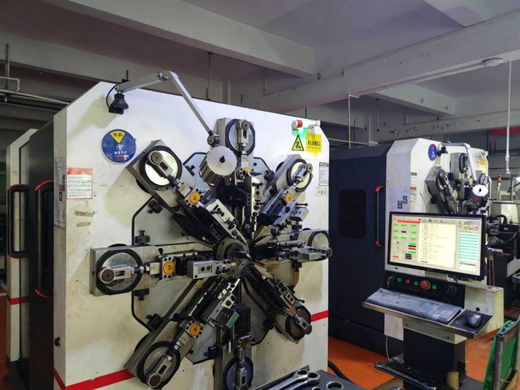
Spring manufacturing starts with the required motion and output. A flat-strip rewind spring and a round-wire compression spring need different geometry, forming steps and acceptance checks. The route must match the drawing and the installed duty.
1. Define the function before choosing the process
Identify force or torque at defined positions, the usable travel or working turns, and the installation space. Show attachments, preload and working direction. These requirements help establish the material condition and geometry to review; a product name alone does not define a manufacturing route.
2. Review material and dimensions together
We work with SUS301, SUS304, SK5, 65Mn and 60Si2Mn, selecting the material for the spring type and application. State the grade if your drawing specifies one, or describe the operating environment and required finish.
Our flat-strip processing range is 0.1–0.6 mm in thickness and 1–100 mm in width, depending on the product. We confirm the available thickness, width and material combination for the design. Wire diameter for round-wire springs is assessed separately.
3. Prepare and form the material
We slit strip material in-house and plan the forming process around the spring profile, attachments and available installation space. Flat-strip and round-wire springs need different forming routes to produce the required geometry.
Our forming equipment includes cam-operated and camless spring machines, as well as compression spring machines. We can also provide stamping for suitable clips and flat parts, with the tooling and process confirmed from the part drawing.
4. Agree the material condition and finish
We carry out setting heat treatment in-house. The treatment is selected for the material and part requirements, while any service-life target is evaluated with the spring’s load, movement and operating conditions.
If your drawing requires a coating or surface treatment, include the specification with your enquiry. We will confirm whether the required process is available for the part and agree its acceptance criteria.
5. Check the part in a defined condition
Dimensions establish fit; force or torque measurements establish output at stated positions. Our inspection equipment includes a hardness tester and a spring tensile testing machine. We also use a force gauge with a suitable reel fixture for checks that represent the spring’s installation.
Tell us the inspection frequency, reports and calibration records your purchase requires so we can agree the inspection plan. For a durability target, include the load, travel, environment and failure criteria.
Prepare the next engineering discussion
Choose power springs for a multi-turn torque discussion, constant force springs for approximately steady pull, or compression and torsion wire springs for the relevant wire geometry.
Review Manufacturing Capability and Quality and Engineering Checks, then use the RFQ checklist to assemble drawings, installation information and quantities. PDF, DWG, DXF and STEP drawings can support review; agree the transfer method for technical files.